The Conversation (0)

Integrated drilling and downhole datasets delineate structurally controlled hydrogen system across multiple domains in Hole 26-02 guiding deeper targeting
Québec Innovative Materials Corp. (CSE: QIMC,OTC:QIMCF) (OTCQB: QIMCF) (FSE: 7FJ) ("QIMC" or the "Company") is pleased to provide an update on the ongoing integrated interpretation of drill holes 1 and 2 from its hydrogen exploration program.
Preliminary results from drill hole 26-02 have identified multiple shallow hydrogen-bearing intervals across a vertical profile extending from near surface to 500 metres depth. The Company's current interpretation indicates that several of these intervals are spatially associated with major structural features encountered in the hole.
Hydrogen and associated gas measurements reported herein were obtained from dissolved gas samples extracted from drill water collected at regular intervals (approximately every 3 metres) at the wellhead during drilling operations. Reported values are preliminary and subject to ongoing integration with geological, structural, geophysical, and petrophysical datasets. Quality control procedures, sensor specifications, and analytical protocols will be summarized in a future technical update.
QIMC is currently integrating geochemical, geological, structural, downhole geophysical, and petrophysical datasets from Holes 1 and 2 as part of its ongoing work to refine its subsurface hydrogen model. Based on results obtained to date, the Company plans to extend drill hole 26-02 beyond its initial 500-metre depth to approximately 700 metres, as the hydrogen-bearing system is interpreted to remain open at depth based on current drilling.
CEO COMMENTARY
"The continued advancement of Hole 26-02, combined with the integrated interpretation of our first two drill holes, marks an important step in refining our understanding of this hydrogen system. We are also pleased to confirm that the drill has been mobilized for Hole 3, marking a significant milestone as we continue to advance our exploration program at pace," said John Karagiannidis, President & Chief Executive Officer of QIMC.
"The presence of hydrogen across multiple domains over a 500-metre interval, together with the structural controls we are observing, provides a strong technical basis to extend the hole deeper. Importantly, the addition of downhole geophysical and petrophysical datasets enhances our ability to characterize permeability, fluid pathways, and subsurface conditions as we advance toward the next phase of our program."
KEY HIGHLIGHTS
Multiple hydrogen-bearing intervals identified from near surface to 500 metres depth
Peak hydrogen concentrations exceeding 1,000 ppmV in selected intervals
Hydrogen anomalies observed in association with major fault zones intersected at 95.0-104.3 metres and 126.8-159.0 metres as well as deeper in domains 5 and 6
Six geochemical domains defined across the current drill profile
Integrated interpretation of Holes 1 and 2 now underway
Drill hole 26-02 planned to be extended to approximately 700 metres
Downhole geophysical and petrophysical surveys completed by SEMM Geoservice, including televiewer imaging, downhole geophysics, H2 measurements, permeability and porosity testing, density logging, and electrical resistivity tomography
PROJECT GEOLOGIST COMMENTARY
"What is particularly significant in Hole 26-02 is the recurring association between hydrogen-bearing fluids and structurally deformed intervals," said Edward Procyshyn, P.Geo., Senior Project Geologist for QIMC.
"The highest hydrogen concentrations are concentrated within the upper portions of the major fault system between 128 and 146 metres, where strong alteration and brecciation are observed. The association of hydrogen with CO and the absence of methane and carbon dioxide in certain sampled intervals is interpreted to be consistent with a deep hydrogen-bearing fluid system. The system is currently interpreted to remain open at depth based on results obtained to date, and the additional downhole datasets are expected to assist in refining permeability pathways and fluid migration models."
Geological Setting
The drill hole intersected a sedimentary sequence consisting of interbedded:
These units are consistent with turbidite sequences comparable to:
Two major fault zones were intersected. These structures are interpreted to represent potential pathways for fluid migration.
Lithology and Structural Observations - Drill Hole 26-02 - Project Geologist Ed Procyshyn
Drill hole 26-02, from a depth of 4 m to the bottom of the hole at 500 m, intersected predominantly sedimentary rocks, with occasional quartz veins and thin (<20 cm) granitic dikes and sills occurring at widely spaced intervals.
Additional shear zones (<25 cm wide), hosting breccia fragments and gouge, were observed at irregular intervals within an otherwise firmly indurated and locally metamorphosed sequence.
Alteration Styles
Two distinct alteration styles are observed within the sedimentary units:
1. Thermal Recrystallization
This alteration is interpreted as a response to a nearby thermal event.
2. Metasomatic Alteration
Hematite (red)
Chlorite (green)
Biotite
Sericite (tan-yellow)
This alteration is typically associated with structurally deformed zones, particularly near faults and shear zones.
SUMMARY OF HYDROGEN RESULTS AND DATA INTEGRATION
Six geochemical domains were defined:
Domain 1 (4-86 m)
Minor hydrogen results
Limited structural influence
The dominant lithology within this interval is recrystallized siltstone, interbedded with sandstone and mudstone. These units are locally brecciated and exhibit crackle textures, with numerous calcite-quartz veinlets (<2 mm thick) occurring at various orientations relative to the core axis.
Recrystallized breccia is interpreted to be sedimentary in origin, containing cherty siltstone clasts up to 3 cm in size within a silica-rich matrix.
Several narrow fault zones containing gouge were identified at:
4.0-5.5 m
7.45-7.53 m
8.65 m (including a ~2 cm gouge zone)
Hydrogen concentrations in this interval are limited.
Although multiple shear zones are present, they appear to post-date the bleaching alteration, and gas samples collected in proximity to these structures are generally barren of hydrogen.
Additionally:
CO is largely absent in this interval
No consistent association between deformation features and gas enrichment is observed
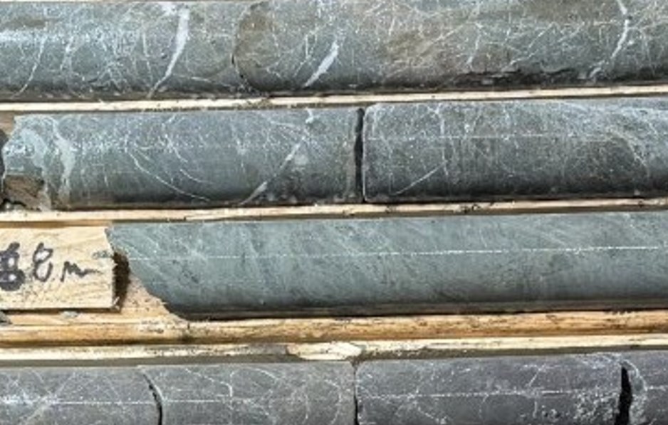
Figure 1: Greenish siltstone and a silty breccia underlain by brownish mudstone are highly recrystallized to develop a cherty texture that subsequently has been highly fractured and veined.
To view an enhanced version of this graphic, please visit:
https://images.newsfilecorp.com/files/7968/292134_fc8988d66470db53_006full.jpg
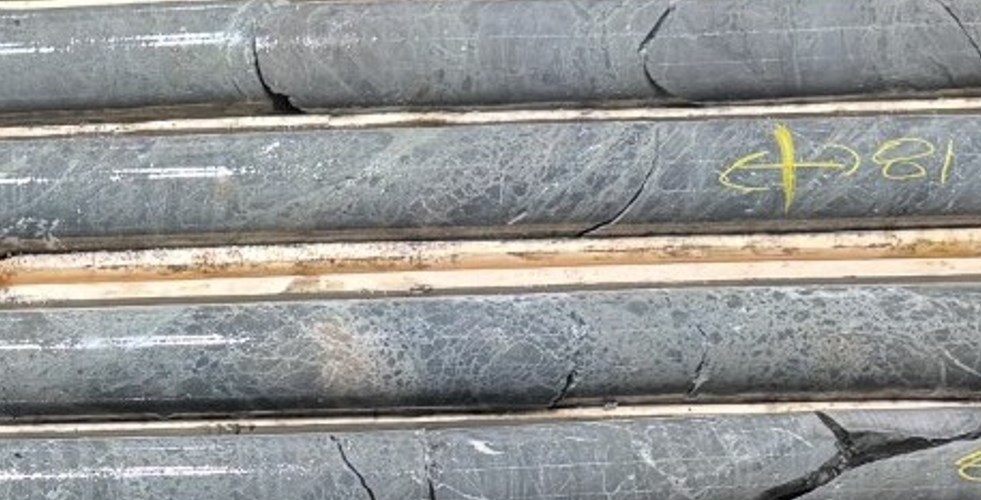
Figure 2: Recrystallized siltstone and siltstone breccia.
To view an enhanced version of this graphic, please visit:
https://images.newsfilecorp.com/files/7968/292134_fc8988d66470db53_007full.jpg
Domain 2 (92-164 m) - KEY STRUCTURAL ZONE
Highlights:
Includes major fault zones
Hydrogen concentrations exceeding 1,000 ppmV
Peak interval: 128-146 m
Lithology and Structural Setting
The upper fault is overlain by green-coloured, silicified siltstone that is strongly crackle-fractured, giving it a breccia-like appearance. The crackle fractures are altered to a pale grey colour and are crosscut by later quartz-filled veins.
The upper fault zone at 95-104.3 m, which consists of:
Crushed rock and gouge
Highly brecciated intervals (~20-30 cm wide)
Broken siltstone and muddy sandstone blocks ranging from 20-60 cm near the top of the fault to up to 1.2 m near the lower contact
At the upper contact of the fault, irregular pinkish-orange carbonate veinlets overprint the green silicified unit.
At the lower contact (104.3 m), a highly altered, massive green micaceous unit is present. This unit is locally cut by irregular quartz blebs rimmed by dark minerals.
The micaceous unit is in contact with a grey sandy mudstone (wacke) containing angular to rounded quartz and lithic fragments (4-6 mm). Fractures within the wacke are lined with hematite.
Downhole Lithological Evolution
The grey wacke grades downhole into:
Featureless green micaceous mudstone
Thin conglomeratic intervals containing irregular white and dark grey lithic fragments, with less common pink granitic fragments
The interval is generally bleached and colour-banded, with green zones (~3 m thick) alternating with pale buff-grey or darker grey bands of similar thickness.
Local shear zones are present throughout.
Gas Geochemistry and Structural Association
At 90.1 m, adjacent to a narrow shear zone containing fault gouge oriented at shallow angles to the core axis, gas extracted from a drill water sample contained:
Elevated hydrogen (>1,000 ppmV)
Measurable CO
This shear cuts recrystallized, crackle-fractured siltstone overlying the upper fault at 95 m.
Within the main fault zone:
Despite intense crushing and multiple shear intervals, the fault core itself shows limited alteration
Gas samples from within the fault core are generally barren of hydrogen
However, at the base of the fault and within the underlying altered green micaceous mudstone, hydrogen concentrations increase:
Primary Hydrogen-Bearing Zone
The strongest hydrogen concentrations occur within the upper portion of the upper fault zone, between 128 and 146 m, where:
Most sampled intervals returned measurable hydrogen
Hydrogen concentrations in some samples exceeded 1,000 ppmV
Below this interval:
Hydrogen values decrease but remain elevated
CO remains absent
Lower Interval Observations
Below the Upper Fault zone the first sample to return an elevated hydrogen value occurred at 164 m depth.
This sample was collected from dark grey conglomeratic mudstone, associated with a 15 cm fault gouge zone at 163.4 m, and underlain by widely spaced (1-1.3 m) foliated conglomeratic intervals.
This marks the first appearance of foliation, characterized by:
Flattened fragments aligned along foliation planes
Foliation oriented at shallow angles (~20°) to the core axis
Bedding typically oriented more steeply (~45° to core axis)
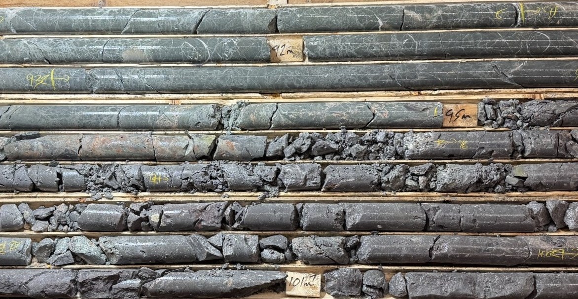
Figure 3: Green siltstone crackle-fractured that are cut by later quartz veins overlie the upper fault zone at 95.0 m. Note the late pink carbonate veins sub-parallel to the core axis.
To view an enhanced version of this graphic, please visit:
https://images.newsfilecorp.com/files/7968/292134_fc8988d66470db53_013full.jpg
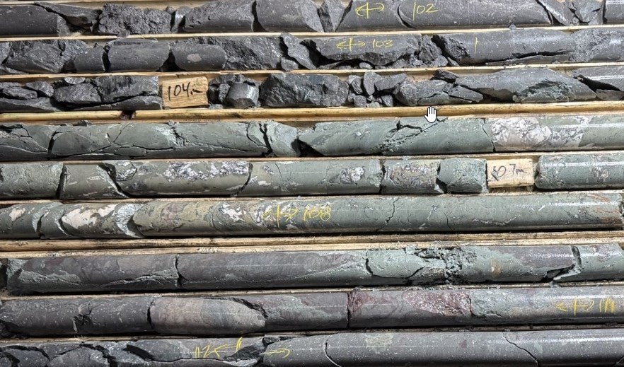
Figure 4: The lower contact of the upper fault at 104.5 m is underlain by green micaceous mudstone in contact with darker grey silty mudstone grading to a grey sandy mudstone containing white rounded quartz and larger lithic fragments. Fractures are lined with hematite.
To view an enhanced version of this graphic, please visit:
https://images.newsfilecorp.com/files/7968/292134_fc8988d66470db53_014full.jpg
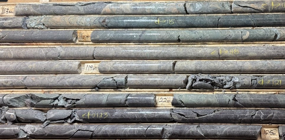
Figure 5: Pale grey muddy sandstone in sharp contact with a conglomerate bed that contains cobble sized irregularly shaped sub-angular pink granite fragments. The conglomerate downhole becomes thinly bed with and passes into a green siltstone that contains a brownish grey mudstone bed ~20 cm thick. The green conglomeratic unit is silicified and bleached to a tan colour and underlain at 121m by a dark grey mudstone interval that again overlies a cobble conglomerate containing grain clasts up to 8 cm across.
To view an enhanced version of this graphic, please visit:
https://images.newsfilecorp.com/files/7968/292134_fc8988d66470db53_015full.jpg
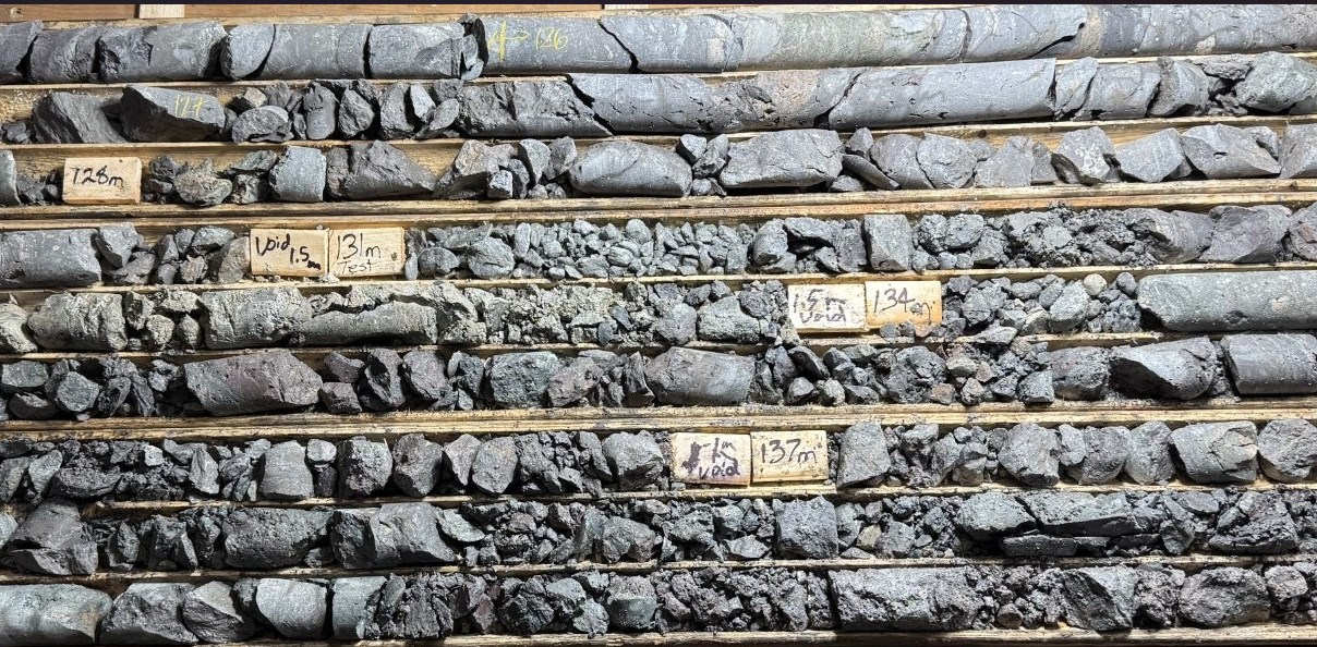
Figure 6: The grey coloured cobble conglomerate overlies the upper fault zone at 126.8 m which extends to a depth of 159 m. Closely spaced faults reduce the rock to rubble, separated by gouge that is now largely washed out by the drill water.
To view an enhanced version of this graphic, please visit:
https://images.newsfilecorp.com/files/7968/292134_fc8988d66470db53_016full.jpg
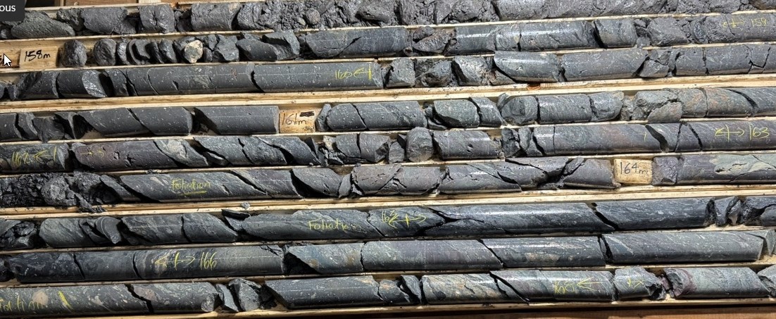
Figure 7: The basal contact of the major fault zone develops secondary shears with gouge <25 cm thick and foliated bands containing flattened fragments aligned along foliation planes.
To view an enhanced version of this graphic, please visit:
https://images.newsfilecorp.com/files/7968/292134_fc8988d66470db53_017full.jpg
Domain 3 (169-209 m)
Highlights:
Lithology and Structural Setting
This interval is underlain by grey to dark grey foliated mudstone conglomerate, containing granule- to cobble-sized fragments. These units are interbedded with occasional coarse-grained sandy mudstone beds (<1 m thick), which locally grade into cherty-textured recrystallized siltstone.
The conglomerates contain:
These fragments are commonly flattened and aligned within foliation planes, forming narrow ribbons separated by dark laminated or mudstone layers (<10 mm thick).
Cobble-sized fragments include pink granitic clasts.
Foliation is well developed in intervals ranging from 25 to 50 cm thick, although shear zones are relatively rare within this domain.
Gas Geochemistry and Distribution
Across this domain:
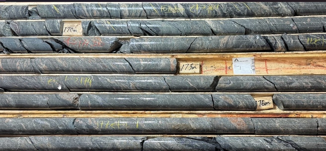
Figure 8: Foliated conglomeratic mudstone interbedded with more homogenous recrystallized muddy sandstone and siltstone. The fragments in the conglomerate range from cobble to granule size and range from white to pale grey to pink in colour. The pink fragments are granite in composition.
To view an enhanced version of this graphic, please visit:
https://images.newsfilecorp.com/files/7968/292134_fc8988d66470db53_020full.jpg
Figure 9: Thinly foliated conglomerate with granule size flattened fragments and occasional larger cobbles of flattened pink granite fragments.
To view an enhanced version of this graphic, please visit:
https://images.newsfilecorp.com/files/7968/292134_fc8988d66470db53_021full.jpg
Domains 4-6 (212-500 m)
Preliminary observations indicate increasing hydrogen content with depth
Full characterization in progress
NEXT STEPS
Extend drill hole 26-02 to approximately 700 metres
Complete integrated interpretation of Holes 1 and 2
Integrate geophysical and petrophysical datasets into targeting model
Drill mobilized for Hole 3
PROJECT GEOLOGIST
The geological content and analytical assessment in this press release was extracted from a report prepared by Edward Procyshyn P.Geo., QIMC Senior Project Geologist. Edward Procyshyn has reviewed and approved the technical content of this press release.
About Québec Innovative Materials Corp. (QIMC)
Québec Innovative Materials Corp. is a North American exploration and development company advancing a portfolio of natural hydrogen and critical mineral projects. The Company is advancing its district-scale hydrogen exploration model across Québec, Ontario, Nova Scotia, and Minnesota (USA), leveraging its proprietary R2G2™ framework developed in collaboration with INRS. QIMC is committed to sustainable development, environmental stewardship, and innovation, with the objective of supporting clean energy and decarbonization initiatives.
For Further Information:
QUÉBEC INNOVATIVE MATERIALS CORP.
John Karagiannidis
President & Chief Executive Officer
Email: info@qimaterials.com
Tel: +1 514-726-7058
DISCLAIMER
Neither the Canadian Securities Exchange nor its Regulation Services Provider accepts responsibility for the adequacy or accuracy of this release.
FORWARD-LOOKING STATEMENTS
This press release contains certain forward-looking statements within the meaning of applicable securities laws. Forward-looking statements are based on a number of estimates and assumptions that, while considered reasonable by management, are subject to business, economic, and competitive uncertainties and contingencies. Forward-looking statements in this release include, but are not limited to, statements regarding the planned extension of drill hole 26-02, the interpretation of hydrogen-bearing intervals, the integration of downhole datasets, and the advancement of the Company's subsurface targeting model. Actual results may differ materially from those anticipated in such statements. Readers are cautioned not to place undue reliance on forward-looking statements. The Company undertakes no obligation to update such statements except as required by applicable law. Hydrogen concentrations reported are preliminary and not indicative of commercial quantities.
Appendix - Technical Reference: Summary of Sedimentary Sequence of DH-26-02
The sedimentary sequence consists of interbedded:
Mudstone
Siltstone
Sandstone (grit)
Conglomerate
These units display variable sorting, grain size, fragment composition, and matrix content.
Muddy and silty sandstone and conglomerate are generally matrix-supported, with framework grains composed of rounded to angular quartz, feldspar, and lithic fragments suspended in a clay-rich mudstone or cleaner siltstone matrix.
Lithic fragments typically include:
Dark-coloured shale-like material
Irregular silicified sandstone fragments
Pink granitic fragments
Grain size varies across the sequence:
Finer-grained sandstones tend to be more evenly sorted and lack clear bedding features
Coarser-grained sandstones are often better sorted and may display thin (<2 cm) intervals of aligned quartz grains, giving a bedded appearance
These coarser units commonly grade into poorly sorted conglomerates, containing angular dark lithic fragments and, less frequently, rounded siliceous clasts within a mudstone or siltstone matrix.
Although some conglomeratic intervals exhibit a breccia-like appearance, they are interpreted as sedimentary due to their gradational transition into finer-grained, bedded units.
Mudstone and Bedding Features
Occasional dark mudstone beds, up to 30 cm thick and lacking visible bedding, occur within more siltstone-dominated intervals. These mudstone units represent a minor component (<3%) of the overall sequence.
In addition, thinly bedded to laminated intervals (1-5 cm thick) of alternating dark and light-coloured layers are observed. These reflect graded bedding, where:
Coarser grains settle first
Finer siltstone transitions upward into mud-rich layers
This pattern is characteristic of turbidite deposition.
Depositional Interpretation
The sedimentological characteristics described above are consistent with graywacke-wacke sequences comparable to those observed in:
The Franciscan Formation (western California)
Ordovician rocks of the Taconic orogen (Appalachian region)
These features are indicative of deposition within a turbidite-dominated foreland basin, where rapid erosion, transport, and burial of uplifted material occur during episodic tectonic activity.
Lithological Definitions and Sedimentological Characteristics
Mudstone is a detrital rock composed of silt-sized particles (5-64 microns; 0.005-0.06 mm) within a clay-rich matrix. It is typically massive and lacks visible bedding laminations or fissility.
Shale refers to a highly indurated, clay-rich mudstone characterized by:
Well-developed fissility
Finely stratified laminae (typically 0.1-0.4 mm thick)
A cherty to hornfels-like texture
Argillite is a compact, weakly metamorphosed rock derived from mudstone, shale, or siltstone. It is more indurated than its parent material, generally massive in appearance, and typically lacks both bedding lamination and fissility.
Slate is a metamorphic rock derived from mudstone, shale, argillite, or volcanic ash. It is characterized by:
Well-developed fissility planes
Alignment of very fine-grained mica minerals (chlorite, biotite, and/or sericite)
Foliation planes oriented independently of original bedding
These fissility planes are typically oriented perpendicular to the direction of maximum compressive stress.

To view the source version of this press release, please visit https://www.newsfilecorp.com/release/292134
News Provided by TMX Newsfile via QuoteMedia